

How to calculate the cooling capacity of a counter flow closed type cooling tower?
Dec 25, 2025
Calculating the cooling capacity of a counter flow closed type cooling tower is a crucial step in ensuring its efficient operation and proper sizing for specific industrial or commercial applications. As a supplier of Closed Circuit Counter Flow Cooling Tower, Counter Flow Closed Loop Cooling Tower, and Counter Flow Closed Type Cooling Tower, I'd like to share some in - depth insights on this topic.
Understanding the Basics of a Counter Flow Closed Type Cooling Tower
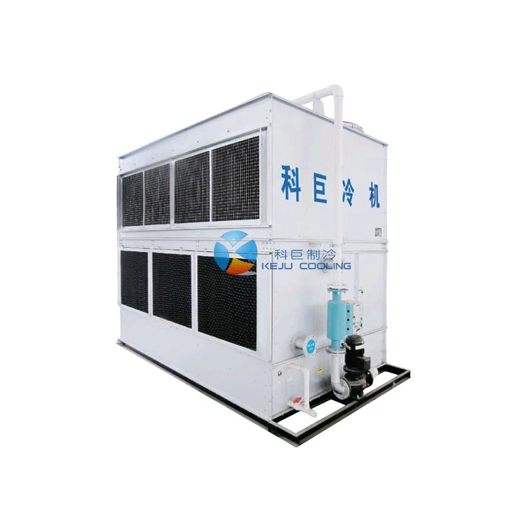
Before delving into the calculation of cooling capacity, it's important to understand how a counter flow closed type cooling tower works. In a counter flow closed type cooling tower, the hot process fluid (usually water) flows inside a closed circuit of tubes, while the cooling air flows in the opposite (counter) direction outside these tubes. The heat from the hot fluid is transferred through the tube walls to the surrounding air and water droplets in the tower.
This type of cooling tower offers several advantages. It prevents the process fluid from coming into direct contact with the environment, reducing the risk of contamination. It also has relatively high heat transfer efficiency due to the counter - flow arrangement of the air and the fluid.
Factors Affecting Cooling Capacity
There are several key factors that influence the cooling capacity of a counter flow closed type cooling tower. These include:
- Inlet and Outlet Temperatures of the Process Fluid: The difference between the temperature of the hot fluid entering the tower and the cooled fluid leaving the tower is a major determinant of the cooling load. The greater the temperature difference, the more heat needs to be removed, and thus, a higher cooling capacity is required.
- Flow Rate of the Process Fluid: A higher flow rate of the process fluid means more heat is being carried into the cooling tower per unit time. Therefore, a larger cooling capacity is necessary to handle this increased heat load.
- Ambient Conditions: The dry - bulb and wet - bulb temperatures of the ambient air have a significant impact on the cooling tower's performance. A lower wet - bulb temperature allows for more efficient heat transfer, as the air has a greater capacity to absorb moisture and heat from the process fluid.
- Heat Transfer Coefficient: This coefficient represents the ability of the tower to transfer heat from the process fluid to the air and water droplets. It depends on factors such as the material and design of the tubes, the air velocity, and the water droplet size.
Calculation Methods
Step 1: Determine the Heat Load
The heat load (Q) that the cooling tower needs to remove can be calculated using the following formula:
[Q = m\times C_p\times\Delta T]
where (m) is the mass flow rate of the process fluid (kg/s), (C_p) is the specific heat capacity of the process fluid (J/(kg·K)), and (\Delta T) is the temperature difference between the inlet and outlet of the process fluid ((K)).
For example, if the mass flow rate of water is (10) kg/s, the specific heat capacity of water (C_p = 4200) J/(kg·K), and the inlet temperature of water is (40^{\circ}C) and the outlet temperature is (30^{\circ}C) ((\Delta T=10K)), then the heat load is:
[Q = 10\times4200\times10=420000\space W = 420\space kW]
Step 2: Consider the Effect of Ambient Conditions
The cooling capacity of the tower is also affected by the ambient air conditions. The performance of the cooling tower is often evaluated based on the approach and the range.
- Range: It is the difference between the inlet and outlet temperatures of the process fluid, which we have already used in the heat - load calculation.
- Approach: It is the difference between the outlet temperature of the process fluid and the wet - bulb temperature of the ambient air. A smaller approach indicates higher cooling efficiency.
The wet - bulb temperature is a critical parameter. Using psychrometric charts, we can determine the saturation humidity and other properties of the air based on the dry - bulb and wet - bulb temperatures. These properties are used to calculate the heat transfer rate between the air and the process fluid.
Step 3: Account for the Heat Transfer Coefficient
The overall heat transfer coefficient (U) needs to be estimated or measured. The heat transfer between the process fluid and the air can be modeled using the following equation for the heat exchanger part of the cooling tower:
[Q = U\times A\times\Delta T_{lm}]
where (A) is the heat transfer area ( (m^2)) and (\Delta T_{lm}) is the log - mean temperature difference. The log - mean temperature difference is calculated as:
[\Delta T_{lm}=\frac{\Delta T_1-\Delta T_2}{\ln(\frac{\Delta T_1}{\Delta T_2})}]
where (\Delta T_1) and (\Delta T_2) are the temperature differences at the two ends of the heat exchanger.

By knowing the heat load (Q) from the previous step, and estimating the heat transfer coefficient (U) (which can be obtained from previous test data or empirical correlations for similar tower designs), we can solve for the required heat transfer area (A).
Advanced Considerations
In addition to the basic calculations, there are some advanced considerations when calculating the cooling capacity of a counter flow closed type cooling tower:
- Fouling and Scaling: Over time, the tubes in the cooling tower can accumulate fouling and scaling, which reduce the heat transfer efficiency. A fouling factor should be included in the calculations to account for this effect.
- Evaporation Losses: Although the process fluid is in a closed circuit, there is still some evaporation of the cooling water in the tower. The energy required for evaporation needs to be considered as it affects the overall heat balance.
- Air Distribution: Uneven air distribution in the tower can lead to reduced cooling efficiency. Computational fluid dynamics (CFD) simulations or wind tunnel tests can be used to optimize the air distribution and ensure uniform heat transfer.
Importance of Accurate Calculation
Accurately calculating the cooling capacity of a counter flow closed type cooling tower is essential for several reasons:
- Energy Efficiency: An undersized cooling tower will be unable to handle the heat load, leading to higher operating temperatures and reduced efficiency of the industrial processes. On the other hand, an oversized cooling tower will consume more energy than necessary, resulting in increased operating costs.
- Equipment Lifespan: Properly sized cooling towers help to maintain the process fluid at the desired temperature, reducing stress on the equipment and extending its lifespan.
- Process Stability: In industrial applications, maintaining a stable temperature is crucial for the quality and consistency of the products. An accurately sized cooling tower ensures reliable operation and consistent performance.
Custom - Designed Cooling Solutions
As a supplier of counter flow closed type cooling towers, we understand that each application has unique requirements. Our team of experts can work with you to accurately calculate the cooling capacity based on your specific process conditions, including the type of process fluid, flow rates, temperature requirements, and ambient conditions. We can then customize a cooling tower solution that meets your exact needs and provides optimal performance.
If you are looking for a reliable counter flow closed type cooling tower for your industrial or commercial application, we invite you to contact us for a detailed consultation. Our sales representatives are ready to answer your questions and assist you in the procurement process. Whether you need a standard model or a custom - designed solution, we have the expertise and resources to deliver a high - quality cooling tower that meets your requirements.
References
- Incropera, F. P., & DeWitt, D. P. (2001). Fundamentals of Heat and Mass Transfer. Wiley.
- ASHRAE Handbook - HVAC Systems and Equipment (2017). American Society of Heating, Refrigerating and Air - Conditioning Engineers.